Search Results
287 results found with an empty search
- Coolpix B500 40X Super-Zoom Camera and Lens Review
I was recently lent a Nikon Coolpix B500, which has a 22.5 mm to 900 mm zoom (35 mm format-equivalent focal length). The lens is actually 4 mm f/3.0 to 160 mm f/6.5 and has a macro mode, as well. I haven’t ever seen a detailed resolution analysis of a super-zoom like this, so I thought I’d take up the job myself. I won’t dwell on the camera features too much, but I can’t help myself from at least making a few observations about the camera body as well. Camera Body Highlights The camera itself is purely amateur; it doesn’t support raw-format (just jpeg) or even manual exposure control. Its 16-megapixel sensor is breathtakingly small: 4.62 mm X 6.16 mm, with 1.34-micron pixels. The pixel count is 4612 X 3468. A modern smart phone sensor actually has bigger pixels than this (typically 1.4 micron). But the camera costs around $300.00 which is cheaper than those smart phones. I’m a big fan of lenses that provide great out-of-focus backgrounds (bokeh). Because of the tiny sensor in this camera, depth of focus is huge until you get to long focal lengths. If you can manage to get the background out of focus, the results are actually quite pleasing. For those of you that are interested, it has both Wi-fi and Bluetooth, and supports SnapBridge. You can do the usual remote control from your smart phone, if you wish. It uses 4 AA batteries (I used rechargeables). The camera, incredibly, is capable of shooting 7.7 frames per second in “sports” mode at full resolution. It can only shoot 7 frames at this rate, however, so its buffer is tiny. Given the lack of a viewfinder, however, you’re pretty much out of luck tracking any action if you zoom in to any significant degree. You can shoot HD video, of course. I’m personally not very interested in video, so I won’t discuss it any further. The ISO range goes from 80 to 3200, but image quality would hover near zero at ISO 3200. The shutter range is from 1 second to 1/5000 second (faster than my D610!). This camera is very, very poor at focusing in dim light and low contrast; it gets ridiculously bad if you get anywhere maximum zoom. This is probably my biggest gripe about the camera. The camera grip is really, really nice; it’s deep and has a very tactile rubberized surface. The camera is very light; a bit too light for my taste. I’m used to the weight of ‘real’ cameras, like the D500 and D610, and I even use battery grips with those. I prefer the inertia and balance that DX and FX camera bodies provide (but I might change my tune at the end of a ten-mile hike). The camera’s lens cannot be manually focused or zoomed, either; you focus with the traditional half-press of the shutter button, and you zoom either by rotating the shutter collar or pressing a lever on the side of the lens. There is no viewfinder, either; only a 3-inch, 921k LCD screen. Good luck finding and tracking a subject in the sunshine. Its big brother, the B700, costs about 50% more; it sports a viewfinder and the usual PSAM controls, plus a 60 X zoom. For about $90.00 you can get a Hoodman Loupe to cover and view the LCD screen in sun (and you can use it on your other camera screens in Live View). Not the most convenient solution, but it works. B500 at 160 mm zoom B500 top view. Really deep grip. B500 articulating 921k 3-inch LCD. No viewfinder. The Lens The lens has a minimum focus distance of 12 inches at 4 mm and a minimum focus of about 11 feet at 160 mm. In macro mode (only at 4 mm) it will focus down to about 0.4 inches! The lens has vibration-reduction (which can be turned off for tripod use), and it works amazingly well. There are no filter threads, and there is no lens hood, either. You’ll need to shade the lens with your hand. It’s theoretically easier to design a lens that only has a small image circle, and this camera sensor only needs a really small lens image circle to cover it. I think you’ll agree that this design theory is in fact borne out with this camera/lens combination when you see the finished results. The focus speed is pretty lazy. The zoom is painfully slow, mushy, and approximate. Once the focus and zoom gets there, the shot usually turns out just fine. I realize that I have been spoiled with high-performance cameras and lenses, but my patience was sorely tested at longer focal lengths and in anything other than bright sunlight. I just have to keep telling myself how inexpensive this rig is. Close Focus A quarter with the macro setting (4 mm) They weren’t kidding about the 0.4 inches lens-to-subject distance in macro mode. Lighting at this distance is truly a nightmare. I had to direct a light beam in at a ridiculously steep angle for the above shot. You can get as snarky as you want about the lighting here; I just wanted to see how close I could get. I’d have to call macro mode largely a hoax. If you can’t illuminate it, you can’t photograph it. And it’s not really magnified that much, either. A bug with any sense of self-preservation would be long gone. Flare resistance is pretty good. 5 mm f/6.4 Flare and Chromatic Aberration Take a look at this sample photo. The lens showed remarkable resistance to flare, even though I pointed the lens right into the sun. Impressive. 160 mm (900 mm FX) f/6.5 chromatic aberration Since I can’t shoot raw format, I can’t tell you if the level of color fringing is due to a great lens design or perhaps in-camera processing. There’s a little purple fringing in the bottom left corner, but no too bad. Shots like this really emphasize any lateral chromatic aberration. People really obsess about the 900 mm FX-equivalent maximum zoom, but I was more impressed with the 4 mm (22.5 mm FX-equivalent) end of the zoom. This lens goes really wide (77.3 degrees horizontal), compared to typical kit zooms that only zoom to 27 mm (67.4 degrees horizontal) FX-equivalent. The more expensive B700 lens doesn’t go as wide at this lens does (73.7 degrees horizontal); I’d much rather have this wider angle ability than a longer zoom. Throughout the entire zoom range, there is essentially zero distortion! The pictures below will demonstrate this. The main weakness of this lens is meridional-direction resolution, which approaches what I’d describe as shameful at longer focal lengths; it’s actually not too bad at the wide end. That 40 X Zoom Wide 4 mm. You can barely see the buildings Telephoto 160 mm I added an arrow in the 4 mm shot to show where I zoomed in. There was a fair amount of atmospheric haze, so don’t mistake that for a flare or lens contrast problem. Now that’s a zoom. Lens Resolution The following resolution analysis was done using jpeg with default sharpening. If it was available, I would have shot in raw and performed the analysis without any sharpening. I use the (free) MTFmapper program, which I describe here. I have a 41” X 60” resolution chart to analyze the lens, except at 160 mm. I would have had to be nearly 200 feet away from the chart at that 900 mm-equivalent focal length to photograph the whole thing; instead I used a small chart that’s only 7” X 10”, at about 35 feet. 41” X 60” resolution chart, 4 mm (22.5 mm FX equivalent) Note in the shot of the resolution chart that there isn’t any observable distortion, judging by the chart edges. I didn’t note distortion (or perceptible vignetting) at any focal length. Please be aware in the following measurements that my usual results, measured in “MTF50 line pairs per millimeter” are highly misleading. I’m accustomed to seeing a good “MTF50 lp/mm” lens measurement peak at 40 to 50; seeing measurements around 300 seems astonishing. But here’s the deal: the camera sensor has a lot fewer millimeters in it, so it’s much less impressive than it sounds at first blush. A better unit of measurement for resolution in this case is “line pairs per picture height”, which gives you the total available resolution in the picture. I have decided to provide 4 different resolution measurement units, so that you can take your pick: “cycles per pixel”, “MTF50 lp/mm”, “line pairs per picture height”, and “lines per picture height”. Besides the 2-D plots across the camera sensor, I looked at the low-level data to provide the peak center and corner resolution measurements. Another little fact to note: the “MTF10/30” contrast plots I have included are based on jpeg with in-camera processing. These plots should really be based upon un-sharpened “raw” files to be directly comparable to other lenses. Since I can’t shoot raw with this camera, I wasn’t given a choice. The contrast numbers look too good to be true, and they are. The plots are at least useful to compare center-to-edge differences and meridional-versus-sagittal performance, too. In the MTF50 resolution plots that follow, “red” is good and “blue” is bad. Unlike most other web sites, these plots show nearly 100% of the camera sensor’s field of view. This lets you evaluate lens resolution across the whole field of view instead of just a slice or a single point. Recall that this camera sensor is about 4.6 mm X 6 mm. The resolution measurements were made with the lens wide-open. Stopping down the aperture will make all of the readings even better. I turned the lens vibration reduction off for these shots, and I of course used a large tripod. MTF50 results at 4 mm f/3.0 The MTF50 lp/mm resolution measurements at 4mm show how much better the lens is in the sagittal direction (think spokes of a wheel) than the meridional direction. 4 mm cycles/pixel Mtf50 lp/mm lp/ph l/ph Center 0.49 368 1699 3399 Corner 0.32 240 1110 2220 4 mm f/3.0 MTF10/30 chart The MTF10/30 chart is misleading, since it’s based upon a jpeg image with default sharpening. Again, this makes the resolution and contrast look better than it really is, when compared to raw, unsharpened shots. I don’t have a choice here, however. The lens meridional direction is consistently worse than the sagittal direction at all focal lengths. When the sagittal and meridional resolution differs by a significant amount, you get astigmatism. You will note that astigmatism starts to become a problem at about 2/3 of the way from the lens center when zoomed to 4 mm. 4 mm corner detail (cycles per pixel on each edge) You can see a huge quality difference when comparing the edges that point toward the image center (sagittal) than the meridional edges. This is why it’s important to analyze the edge directions separately. Notice in the picture above the minimal chromatic aberration, which gets emphasized in a high-contrast shot like this. MTF50 results at 17.6 mm (99 mm equivalent) f/4.6 17.6 mm cycles/pixel Mtf50 lp/mm lp/ph l/ph Center 0.38 285 1318 2636 Corner 0.33 248 1144 2289 17.6 mm f/4.6 MTF10/30 chart At 17.6 mm (99 mm equivalent FX) the resolution is just plain spectacular. Astigmatism is very well controlled. MTF50 results at 35.9 mm (202 mm equivalent) f/5.4 35.9 mm cycles/pixel Mtf50 lp/mm lp/ph l/ph Center 0.41 308 1422 2844 Corner 0.34 255 1179 2358 35.9 mm f/5.4 MTF10/30 chart Very, very good resolution at 35.9 mm. MTF50 results at 52 mm (294 mm equivalent) f/5.7 52 mm cycles/pixel Mtf50 lp/mm lp/ph l/ph Center 0.41 308 1422 2844 Corner 0.34 255 1179 2358 52.2 mm f/5.7 MTF10/30 chart Meridional resolution is taking a nosedive in the corners here, but sagittal resolution is excellent. MTF50 results at 70 mm (394 mm equivalent) f/5.9 70 mm cycles/pixel Mtf50 lp/mm lp/ph l/ph Center 0.40 300 1387 2774 Corner 0.31 233 1075 2150 70.0 mm f/5.9 MTF10/30 chart Again, meridional performance in the corners is pretty bad, but the sagittal performance is great. MTF50 results at 160 mm f/6.5 160 mm cycles/pixel Mtf50 lp/mm lp/ph l/ph Center 0.27 203 936 1873 Corner 0.21 158 728 1457 160 mm f/6.5 MTF10/30 chart Performance takes a giant hit at maximum zoom. Be that as it may, check out the shot below of the moon at 160 mm; it may not compete with ‘pro’ monster lenses, but it still looks pretty good. Samples 160 mm (900 mm equivalent) f/6.5 1/1000s ISO 125, un-cropped Rufus hummer detail crop The default in-camera noise reduction slightly smears fine details, even at low ISO and bright light. The majority of the ‘smearing’ is probably the meridional-direction weakness in the lens, however. 160 mm f/6.5 1/250s ISO 125, slightly cropped. The moon shot was hand-held at maximum zoom. Kudos to the VR system in this lens! Considering the maximum zoom being used and that I hand-held the camera, these results are nothing short of fantastic. 5 mm f/3.2 1/125s ISO 125 Summary There are certainly limitations with the B500 camera, but it is capable of very high quality photographs. Keep in mind that this camera/lens combination costs less than many DSLR kit lenses! It’s hard to draw any blanket conclusion on this camera. It has a weird mix of really nice and really irritating features. Personally, I require more direct control (P, A, S, M) than this camera provides, and I really missed raw-format files. The lens, however, exceeded my expectations; with a bit of coaxing, it’s possible to take really nice pictures with the B500. #review
- Remote Camera Control Using digiCamControl
When you control your camera via a cable to your computer, it’s called tethered capture. The two most popular communications cables are Ethernet and USB. This article reviews a tethering program called digiCamControl, which uses USB for remote control. I was also going to review tethered capture using LightRoom, but that program is so pathetic at remote control that I decided to not bother. Most people would use a program like this in a studio environment, but it can also be very useful for situations such as shooting from a blind. It's possible, using USB hubs, to 'daisy chain' USB cables together and extend the cable length. I want to concentrate on this program’s ability to perform automatic focus-stacking, which I’ll cover in some detail. The (free) digiCamControl program has a full complement of camera controls, live view, automatic photo transfer to your computer, exposure bracketing, time lapse (movies), web-server remote control (e.g. your smartphone), focus-stacking, multiple screen control, and motion detection. This is a Windows program, and supports most Canon, Sony, and Nikon DSLR/mirrorless cameras (about 100 models). I’m using it with a Nikon D500 and Windows 10. It can be downloaded from here: There is some online documentation, but I don’t consider it very thorough. digiCamControl startup screen after turning camera on When you first start up digiCamControl and turn on your camera, you’ll see something like the screen above. You could start taking pictures by clicking the “aperture” icon in the top-left, but you don’t necessarily know if the camera is in focus yet. The program seems pretty forgiving about turning your camera on before or after starting digiCamControl. The Nikon camera LCD panel shows “PC” to indicate the camera is connected to the computer (via the USB port). digiCamControl main screen after “Capture” click The main reason to use this program is to see a big, beautiful live image on your computer screen, so I go straight to the “Live View” screen, by clicking the “Lv” button. Don’t invoke live view from your camera. You can still use your camera’s shutter release even while connected to the computer. You have full control over exposure, white balance, ISO, and focus from your “Live View” screen on your computer. Download from camera memory card You can separately download pictures from your camera memory card (the main screen “download” button) which will give you thumbnail views of what’s on your camera. Live View screen in digiCamControl The camera LCD doesn’t display its live view, so it doesn’t get hot or consume unnecessary batteries showing you what’s already on your computer screen. Your “live view” is just on your computer’s screen, where you want it, after you click on the “Lv” button. You get a histogram while in live view, too. Click with the left mouse button on the live view screen where you want the focus point located, and then you can click on the “Autofocus” button to focus there. You should see a green square around the focus point location. By default, your pictures will go directly to your computer, such as C:\Users\Ed\Pictures\digiCamControl\Session1 You can assign the session name where you want the photos to go. Since they go to your computer, you’re essentially unlimited for storage. There is pretty significant battery drain while remotely controlling your camera; it’s handy that the battery level is displayed on the main screen. Use a battery grip to make battery drain less of an issue. Live View Exposure Controls The screen shot above shows how you can set your camera controls from the Live View “Control” dialog. Motion Detection and Intervalometer Motion trigger and intervalometer You can trigger your camera via motion detection from Live View, as well as take a series of timed shots (intervalometer). Focus Stacking When you want to stack photos to increase depth of field (even including a landscape shot), you may just fall in love with this program feature. digiCamControl gives you great control over how to configure the near-limit, far-limit, and number of shots in-between for stacking photos. Session setup Start by clicking the “Session” menu option from the main screen, then “Add new session”. Fill in a session name and browse to the folder where you want to save the focus stack photos. A session lets you organize your shots into logical groups. Once you click the “Lv” button from the main menu, you enter “Live View”. You may need to “maximize” the live-view screen to see it. Click on the live view screen with your mouse where you want the “near focus” focus point to be (a green square). Click on the “Auto focus” button to focus on that spot. Advanced Focus Stack dialog Click the (screen top) “Preview” button and then use the mouse wheel to zoom in on the focused spot to verify critical “near” focus. Click on the Preview Screen “X” to close the “preview” dialog and return to live view. Refocus if necessary. Use the bottom-center buttons to rough-focus (the “<<<”, “<<”, ”<”, ”>>>”, ”>>”, ”>” buttons) where more arrows focus in larger steps. Click on the left-hand “lock” button at the bottom of the screen to prevent the near focus from changing any more. Use the same arrow controls to obtain the “far” focus desired, and then click on the right-hand “lock” button at the bottom of the screen to prevent changing the far focus any more. Now that the focus range is locked in, make sure that you expand the “Focus Stacking Advanced” on the left edge of the Live View screen. Enter the desired number of photos, the focus step size (start with around ‘30’) and the wait time between photos. Click the “Preview” button, just below the “Focus Stacking Advanced” controls. This will let you automatically run through all of the focus steps before actually taking the photos (near-to-far), showing the count number as it steps through your requested number of shots. If it looks good, then click on “Start” to let the photo sequence get captured to your computer. Although the digicamcontrol program includes the “enfuse” plugin and can discover other plugins (my CombineZP, for instance) I got errors when I tried to use the plugins. Personally, I use the free stand-alone CombineZP program directly for my focus stacking. The screen shot above shows the Live View screen while setting up the “Focus Stacking Advanced”. The screen shot was done after locking in the “far focus” position; you can see how the near focus looks very fuzzy. After letting digiCamControl control the camera to take the 9 requested shots and saving them to my requested computer folder, I ran the CombineZP program (very similar to the older CombineZM) to stack them into a single shot, as shown below. If you’re interested, I made an article on focus-stacking here: Stacked result from 9 shots: CombineZP “soft stack” I might mention that if you haven’t used focus-stacking software before, you need to make your photo-framing a little wider than what you want for the finished shot. The photo edges will show some unwanted artifacts that are related to shifting focus in each shot. Note the bottom of the photo above shows a “mirror image” that should get cropped off in your editing software. Conclusion There is plenty to explore in this tethering program. Many of its features, such as bracketing exposure, can be done more easily in-camera. Focus-stacking, however, is what I consider a real forte of this program. #howto
- How to Measure Lens Vignetting
How dark are those corners in your photos, by the numbers? How much do you have to stop down a lens to lighten the corners? You can get the answers for yourself using a variety of image editors. The only special equipment you probably need is a grey card or a subject with neutral tones and even illumination. If you want to explore how vignetting changes from close-focus to infinity, then you can photograph the clear blue sky for a target (unless your lens is a super-wide). I’ll show you in three different image editors how to measure RGB values. Capture NX-D example to get RGB values (resolution chart photo) The mouse cursor location is used for RGB value feedback in Capture NX-D. It is shown on the bottom edge of the window. Zoner Photo Studio Pro shows RGB and cursor X,Y The Editor in Zoner Photo Studio Pro displays both the cursor location and the RGB values while using the “magnifying glass” cursor, for instance. Photoshop example using a grey card target Shown above, you can use Photoshop to sample locations of interest from a photo of a grey card. Here, I selected a point near the center and a point in a corner. I used the “color sampler” to get the RGB values. Make sure you have correct white balance, so that the R,G, and B values match (or they're at least close) when using your grey card. The selected central point in the example has an average of 158 for the RGB, while the corner point has an average of 79. You would probably assume that with values that are half as big, there would be a one-stop difference between the center and the corner. But life isn’t quite that simple. The RGB values are non-linear in response to brightness. The use of a grey card makes viewing the lighting distribution across a photo much simpler. Since the RGB relative values should be pretty close to the same at any selected location with a neutral grey card, the overall evaluation of vignetting is just easier (R=G=B in daylight with proper white balance). My resolution charts also work well for this purpose. The gray card analysis above was done using the Nikkor 18-140 f/3.5-5.6 wide open at f/5.6 and 140mm. This is the lens pretty much at its worst. This happens to be my worst lens for vignetting that I own. Stopping down quickly minimizes whatever vignetting there is, by the way. So, how do we use these RGB values to get F-stop values? As I mentioned above, the RGB values don’t relate in a very straightforward way to F-stop values. One way to solve the problem would be to start by setting your camera on ‘manual’ exposure, and take a set of RAW-format pictures of a gray card. Start with a photo that’s about 3 stops over-exposed, and then change your exposure (aperture or shutter) by a third of a stop for another shot. Keep this up until your last shot is at least 3 stops under-exposed (a total of 19 shots). For Ansel Adams fans, this would be shots from Zone 8 through Zone 2. In your photo editor, you can then read the RGB values of each shot to note the progression. If any shots have a “255” RGB reading, then you’ve got a blown-out photo and you won’t be able to use it. There are few lenses that have more than 3 stops of vignetting. With this exposure shot collection, however, you should be able to use these RGB values for more than just vignette analysis. Your library of 1/3 stop photos and their RGB values will let you later analyze any photo where you want to critically analyze brightness and contrast ranges in terms of F-stops. For my own tests, I changed the shutter by third-stop values all the way from +3 stops through -5 stops (Zone VIII through Zone 0). I used the “ExifTool” program explained here to get the “Light Value” (or “EV”) in each shot, to get a list of decimal numbers for easy math with the “stops”. I then used a photo editor to get the RGB for each shot (it varies a little bit in each shot, so I noted a typical value, where R=G=B). Notice that the Zone VIII shot is close to the 255 maximum. Stops Zone EV RGB +3.0 VIII 2.7 250 +2.7 3.0 239 +2.3 3.3 234 +2.0 VII 3.6 225 +1.7 4.0 215 +1.3 4.3 200 +1.0 VI 4.6 180 +.7 5.0 160 +.3 5.3 140 0 V 5.7 125 -.3 5.9 105 -.7 6.3 85 -1.0 IV 6.6 70 -1.3 6.9 60 -1.6 7.3 44 -2.0 III 7.6 40 -2.3 7.9 37 -2.7 8.3 33 -3.0 II 8.6 28 -3.3 9.0 24 -3.7 9.3 22 -4.0 I 9.6 21 -4.3 10.0 19 -4.7 10.3 15 -5.0 0 10.6 13 Given the EV-RGB list above, let’s get back to the lens vignetting problem. The lens center measured about 158 (R), and the corner was about 79. This relates to roughly EV 5.0 and EV 6.4, for a difference of about 1.4 stops. I noticed that the DxOMark site rated this lens vignetting at “1.2 stops”. Pretty close. Exposure Value versus RGB value You can see how non-linear the RGB values are, compared to the EV. It’s well-known how the numeric separation is large in bright areas and small in dark areas. Conclusion I tried the experiment above on a couple of different computers and in three different image editors; the results were in close agreement on each. You could probably just use the results of my experiment directly for your own lens vignette analysis. #howto
- Keeping up with MTFMapper: any MTF you Want
Since I use it so much, I like to keep readers aware of new features in the MTFMapper program available here, written by Frans van den Bergh. As of this writing, his latest version is 0.6.18. My own favorite features of this program are focus measurement and 2-D resolution plots. I suspect that many users are big fans of being able to make their own MTF contrast plots, however. MTF contrast plots are by far the most popular way to compare lenses, and they’re still basically the only way to get lens performance data from most manufacturers. If you keep up with Roger Cicala at LensRentals.com, you’ll know that he always includes these plots in his lens reviews. Roger has started to always include these MTF contrast plots at resolutions up to 50 lp/mm. This decision is probably driven by modern camera sensors having so much more resolution than in times past; MTF30 just doesn’t cut it anymore. The MTF contrast plots provide a quick analysis of the level of percent lens contrast at a particular resolution; they start at the lens center, and extend to the corner of the field of view. They traditionally measure in both the meridional and sagittal (tangential) directions. MTFMapper 0.6.18 now lets you produce MTF contrast plots with your choice of resolutions! Instead of its default of 10 lp/mm and 30 lp/mm, you now get to pick what resolutions you want plotted. But wait, there’s more. Now, you can add a third plot at yet another selectable resolution. Sample MTF contrast plot at 10, 30, and 50 lp/mm To produce a plot like the sample shown above, you need a photograph of a resolution chart. MTFMapper is very flexible in what your chart design looks like; it basically only needs to see black rectangular shapes (or even trapezoids) against a light background. The program locates the straight edges of the rectangles and takes a measurement of every edge. Once you open the desired chart photos and let the program crunch the measurements, select the “lensprofile” of your photo to see the MTF contrast plots. Configure MTFMapper for MTF contrast plots Before you can produce the contrast plots, you need to tell the program what you want. The Preferences dialog shown above demonstrates how you provide that information. Your answers would be garbage unless you enter the correct “pixel size” microns for your camera. You can see above that I added the “lp1”, “lp2”, and “lp3” arguments to get all three MTF contrast plots. I wanted the “10”, “30”, and “50” lp/mm measurements. You’re free to select 1, 2, or 3 plots at resolutions of your choice. The program won’t stop you from selecting something like “—lp3 60” to get a 60 lp/mm plot. Not many of today’s lenses/sensors can perform at this level, but if a manufacturer will make them, then MTFMapper could measure it. Just for fun: MTF contrast plot at 10, 40, and 60 lp/mm. 105mm f/2.8 Micro-Nikkor The 105mm Micro-Nikkor measurement above looks pretty bad on that green plot, until you realize that it’s at 60 lp/mm. This is using the Nikon D610 (5.95 micron pixels). I wanted to mention that you can get the MTF contrast information for a particular edge in a particular location in the field of view, if you wish. For this information, you’d select the “annotated” information for your photo. Locate the edge you want to analyze, and then left-click the cyan-colored measurement. A plot will get displayed. You can hold the “shift” button down and get up to 3 plots of 3 edges to be displayed at once. The dialog is called “SFR/MTF curve”. The “SFR” letters stand for “Spatial Frequency Response”, and that’s a synonym for “Modulation Transfer Function”. MTF curve details for a single edge in the resolution chart The shot above shows how you can zero in on a single edge for very detailed analysis. In this example, I was interested in the “MTF30” (30% contrast) frequency in the meridional direction, so I dragged the gray bar to where it displayed the contrast “0.299”, and that corresponds to a frequency of 0.4 cycles per pixel. Knowing the sensor pixel size (5.95 microns), the 0.4 c/p frequency value can be converted into “line pairs per millimeter” resolution as follows: Lp/mm = (c/p) * V_Pixels / V_mm, where the sensor is 4016 X 6068 pixels, 24.0 mm X 35.9 mm MTF30 lp/mm = .4 * 4016 / 24 = 66.9 Similarly, the MTF50 lp/mm on this edge (50% contrast) would be 0.287 * 4016 / 24 = 48 You can save the plot image (click “Save image”) and you can also save the plot data as “comma-separated” data for use in Excel. Other new MTF Mapper Features This version of the program, when you use the newest resolution chart design at the recommended shooting distance, lets you get very detailed information about how your camera is aligned to the chart. Newest resolution chart with the round “fiducials” The example shot above (taken from Frans’ documentation) shows how you can get feedback about how the chart is oriented, compared to your camera sensor. The smaller roll, pitch, and yaw readings you can get, the better-aligned the chart is. As I already mentioned, the MTFMapper can use older resolution charts for performing resolution analysis. If you print the newest resolution chart, however, you can get additional features. In the sample shown, the “Yaw = 2.68” indicates that the chart is rotated about a vertical axis such that the right-hand side is further from the camera than the left-hand side. If you have trouble reliably mounting your chart in front of your camera, then this feature could be really useful to you. Please don’t forget to read the “help” documentation that Frans includes with his program. It is packed with useful insights into the “how and why”. Conclusion If you have the inclination, this newer version of MTFMapper should enable you to compare your own lens copy to other web sites, when they only provide MTF contrast plots. Keep in mind that some web sites (like LensRentals) only measure the lens and don’t include the camera sensor. If this is the case, then your own measurements won’t look as good; the camera sensor always drags the measurements down a little bit. Thanks once again, Frans. #review
- Portrait Retouching Using Masks
If you want to make friends, learn how to retouch a portrait. Nobody likes themselves as-is, despite what they may say. It’s often been said that your goal should be to make a person look 10 years younger, but not more. If you go too far with retouching, you’ll make a portrait that looks completely fake. You won’t get thanked for that. On the other hand, it’s commonly expected that portrait photographers are also dermatologists, plastic surgeons, dentists, and opthalmologists. You will be doing yourself a favor if you shoot your photographs using camera picture controls such as “portrait” or “neutral”. Avoid “vivid” like the plague. My favorite is “neutral”. Use a slightly-long lens, like the classic 85 mm, to get a pleasing perspective. Back in the day, the 105 mm was king; it’s still a great choice for portraiture. Face parts have many completely opposite requirements; some need sharpening and others need softening. Some parts need more saturation, some need less saturation. To meet these contradictory retouching needs, the best tool is the mask. Many image editors support masking. I’m still a die-hard Nikon Capture NX2 fan, so I’m going to concentrate on how that program uses masks. Lightroom (ala the ‘Adjustment Brush’) has masks. Lightroom’s “Auto Mask” can select non-circular shapes by looking for similar coloration, but I find their masking a bit too limiting. This is probably my least-favorite program for masks. Photoshop, of course, has masks. It has always struck me as being just a bit too complicated and time-consuming for my taste, but that may be because I haven’t invested sufficient time in it. If you’re comfortable with it, then by all means use it. Zoner Photo Studio Pro supports masks via the “Selection Brush”, lassos, circles, rectangles, etc. along with “Mask: Do Not Show”, “Mask: Normal/Inverted” etc. Similar to Capture NX2, you can soften the edges of the selection and erase your selection mistakes. Once you make your mask, you can apply softening, sharpening, or other effects that only affect what’s inside the mask. Zoner Photo Studio Pro mask in the “Editor” tab Zoner Photo Studio Pro masking example using the Brush Selection Portrait Retouching Using Nikon Capture NX2 I want to show you how I use Capture NX2 to accomplish retouching, but I’ll let you pick your own favorite editor to get the same job done. I realize that Capture NX2 is now un-supported by Nikon. If you want to keep using it with your RAW images, then you can check out this article to convert your newer camera files into a RAW format that Capture NX2 can understand. In this program, you perform mask selection/ adjustment pairs. After the adjustment, you click on “New Step”. Next, you select another mask and the adjustment associated with that mask. Mask Tools You need to know how to add a selection mask and, just as important, how to erase a selection mask. Some picture details, such as the corner of an eye, would be extremely difficult to accurately select in a single step. The mask selection brush is typically too wide to easily get into little nooks and crannies. Constantly adjusting the mask brush diameter is horribly inefficient and a losing proposition. It’s much easier to paint outside of the lines, and then switch to the mask “eraser” to clean up your mask. Capture NX2 mask controls: Add and Subtract Don’t be afraid to use a mask that goes beyond the area you want Switch to the mask “eraser” and clean up the corners Finished mask after erasing around the nooks and crannies Retouching Teeth Few people have really white teeth. Nobody has perfectly-white teeth. When retouching, you need to “de-saturate” them and also brighten them. Don’t go too far with this. You want to reduce yellowing by lowering their color saturation, which will leave teeth looking gray. Next, you need to brighten the teeth (without making them pure white). You want to select only the teeth to whiten and brighten them Paint the mask (green) over the teeth in Capture NX2 After you mask an area, you will need to make it invisible while you apply an adjustment. In Capture NX2, you hide the mask by changing the selection from “Show Overlay” to “Hide Selection” as indicated by the arrow in the picture above on the right-hand side. Fine-tune the saturation After you use the “Selection Brush +” to mask only the teeth, select the Saturation/Warmth adjustment. Avoid 100% opacity, or your edits will look a bit “fake”. Also adjust the mask feathering, to avoid hard edges. Change the mask selection from “Show Overlay” to “Hide Selection” to see the progress of the saturation effect. If you make mistakes while painting the (green) selection mask, simply click on the “Selection Brush –“ to erase the parts of the mask that you don’t want. Masks don’t have to be continuous, so that you can do things like selecting both eyes. Teeth after de-saturation. Gray is better than yellow, but not by much. Change the mask selection to “Hide Selection” while adjusting the saturation (or to see any effect you’re working on). The teeth may still look a little disappointing, since they changed from yellow to gray. Not to worry. Increase brightness, but with a mask selecting only the teeth. Choose the Brightness adjustment, while using the mask over the teeth. Change the mask to “Hide Selection” again, while increasing the brightness. Avoid the temptation to over-brighten the teeth; real teeth are slightly yellow and slightly gray. When you’re happy with the way the teeth look, click the “New Step” to finish (assuming you’re using Capture NX2). Fixing Eyes Most eyes need three different adjustments. The iris typically looks better when its color is more saturated. Similar to teeth, the whites of the eyes may need some de-saturation and they always need brightening. You also want the eyes, brows, and lashes to be very sharp (via the ironically-named un-sharp mask). Eyes with typical issues that need improvement Mask used for brightening and de-saturation of any red color Eyes and brows need extra sharpening A portrait just won’t look good if the eyes, lashes, and brows aren’t sharp. Make a mask for them and apply the Unsharp Mask. Repair Eye Bags Bags under the eyes are typically a two-step process. First, they usually need more Gaussian Blur than the rest of the face, and possibly even some Healing Brush. They usually need extra brightness adjustment, too. Make a separate mask for enhancing under the eyes If makeup isn’t used under the eyes, then they usually need to be brightened and have a little healing brush applied. The brightening needs a mask, but the healing brush doesn’t. Skin Here’s some advice: don’t go crazy with the “Healing Brush”. You can waste a lot of hours trying to heal every blemish on an entire face. Try this instead: Gaussian Blur. You’ll find that you can usually hide skin blemishes in a single step by simply blurring the skin. Moderation in all things. You really, really don’t want “Barbie Skin”. When you apply Gaussian Blur, remember to adjust the opacity away from 100%. Skin shouldn’t look blemish-free. And feather the mask edges, too. For males, you’ll generally use much less blur. Make a face mask that avoids the eyes, brows, nostrils, and mouth Perhaps the biggest improvement in most portraits is getting the skin blurred. This does not include the eyes and mouth, however. Gaussian Blur for the skin The Gaussian Blur can be pure magic. Again, don’t forget to allow a little of the original skin to show through. Keep the opacity around 80 percent, and use a generous “feather” for the face mask. Use a large enough blur radius to hide blemishes, but avoid making the skin look fake. Conclusion Portraits typically take more editing work than any other type of picture. Most pictures work just fine with ‘global’ adjustments, without any masking at all, but pictures of people rarely look good with this treatment. A good job of portrait editing leaves the viewer with a sense that something’s different, but they can’t really put their finger on it. Cosmetics and good lighting can certainly help portraits and reduce the retouching labor, but there’s really no substitute for skilled retouching. #howto
- The History of MTF50 Resolution Measurement
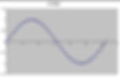
I thought it might be fun to give you a little insight into how some really smart people figured out how to use computers and math to automatically measure lens resolution. Believe it or not, some of the techniques being used date back to the early 1800’s! It all began with a guy called Jean-Baptiste Joseph Fourier, who was born in 1768. Fourier started looking at how you could combine different combinations of “sine waves” to approximate virtually any curve with a repeating pattern. So, what’s a sine wave? A sine wave, using “radians” The picture above shows the simplest sine wave, which is a “trigonometric function”. This is a function that smoothly changes value as you travel around a circle and varies between positive one and negative one. You’d call this a “single cycle”, or a wave (sort of looks like a water wave cross section). If you imagine the hour-hand on a clock (with a length of 1 inch) running backwards, think of horizontal as zero height (3 o’clock and 9 o’clock). It’s “+1 inch” at 12 o’clock and it’s at “-1 inch” at 6 o’clock. That’s the basic sine wave function. By the way, there’s a closely-related function called “cosine”. The cosine is basically the same, except that the wave is shifted by -90 degrees relative to the sine wave, which is called a “phase shift”. Radians, by the way, are just another way of measuring rotation around a circle. “Pi” radians (3.14159) are the same as 180 degrees. Radians are used more in math and physics, because they’re a more “natural” unit of measure. A sine wave with twice the ‘frequency’ Now, I’m showing you a wave with twice as many oscillations as the first one, or twice the frequency. It varies between the same values (plus one to minus one), but twice as often. More waves within the same distance are what are called “higher frequency”. Taller waves are said to have higher “amplitude”, or higher “intensity”. Add the two sine waves together Fourier noticed what a weird result you can get when you add together multiple waves (a series of sine waves). He discovered that he could construct a line shaped like anything he wanted, if he added enough sine waves (each with a different frequency), together. This “Fourier series” he invented (and announced in 1807) has morphed into a “Fourier Transform”, and it’s used in many fields that one way or another relate to “waves” and frequency analysis. Fourier discovered that making functions that rise up and then fall down more steeply took higher-frequency sine waves to replicate that shape. Think of the Fourier Transform as a technique to break down a function into its component frequencies. There’s a deep connection with the way nature works and Fourier’s multi-frequency wave addition. White light, for instance, is comprised of a continuous spectrum of different frequencies of electromagnetic radiation. Brighter light doesn’t mean higher frequency; it actually means that the waves have higher amplitude, or intensity. This also means that you don’t have to worry about how bright the light is when you try to measure resolution. Some smart guys (Cooley and Tukey) figured out how to write algorithms that implement Fourier transforms in a very fast way, so of course they called them “Fast Fourier Transforms” or FFT’s. These FFTs get used today in lens resolution analysis programs (and in many other places, too). It turns out that Carl Friedrich Gauss in Fourier’s time actually invented the FFT, but it was lost to history and re-discovered in 1965. Many disciplines in math, science, and even photography discovered how useful Fourier transforms could be. They could transform “spatial domains” (positional information) into the frequency domain. The next discovery, called the “inverse Fourier transform”, lets you go the other way, from the frequency domain back into the spatial domain. The old ‘manual’ way to estimate resolution Take a look at the resolution chart above. This is an example of how resolution was estimated before computers and modern measurement techniques. You would photograph the chart, and then try to figure out where the converging lines would turn to mush, and call that your lens resolution. On the plus side, this works as well for film as it does for digital cameras. On the negative side, you now have to control how far away you are when you photograph the chart, it’s slow and tedious to use, and you only get an idea of lens performance in a couple of places in the field of view. One thing that’s made of “waves” is light. The job of a camera lens is to gather and re-direct light waves onto a camera sensor. A really good lens can efficiently react to variations in light, such as the edge of a black square against a white background. If you have a lens with ‘perfect’ resolution, then a photo of a black square against white won’t show any ‘gray zone’ between the black edge and the white background. Reality steps in and rears its ugly head, however, and your photo shows a small zone of gray between the white background and the black square. Plot of light intensity between black square edge and white background If you were to graph a plot of light intensity as you move from the white background onto a black square, you’d notice that good lenses have a plot that lowers quickly (spanning a small number of sensor pixels), whereas with poor lenses the plot would lower much more gradually. If you continuously plot moving over this edge back-and-forth, the plot would look similar to the sine-wave patterns above, but with a steeper rise and fall than those low-frequency waves have. I mention the ‘back-and-forth’, because you’ll recall that the Fourier series only works with repeating patterns (ala waves). Combined intensity plots with a flip in-between. Becomes a ‘repeating pattern’. If you were to perform a Fourier analysis on this repeated rise and fall pattern of light cycles, you could discover how it requires higher-frequency sine waves in the series to approximate the original pattern. A good lens would require a higher frequency set than a poor lens to model the response; we call the response “cycles per pixel”. It generally takes several camera pixels to contain an entire dark-to-light transition cycle of an ‘edge’ photo, so the number of “cycles per pixel” is a value that’s less than one. Lo and behold, you now have a way to evaluate resolution in “cycles per pixel”, thanks to Fourier. The real magic of using these Fourier Transforms is that you can perform the analysis given only a single edge. As a side note, if your lens is out of focus, then the light-to-dark transitions are less steep. This would result in a lower resolution measurement. It’s very important to have your lens in sharp focus while testing it, or else you’ll get a wrong resolution measurement. Subject or camera motion can also mess up resolution measurements, but probably more in one direction than the other. Once you know the “cycles per pixel” resolution and the dimension specifications of your camera sensor, you can easily convert this number into other measurement units, like “line pairs per picture height”. Now, imagine you photograph a series of lines, like a picket fence. A good lens/sensor combination would enable you to record a full transition from light-to-dark (a light “modulation”) on the edges of each picket. If the pickets get too close to each other, however, the light-to-dark doesn’t get to finish before the sensor sees the neighboring picket. If the light-to-dark transition only gets half way to “dark” between closely-spaced pickets (or 50% contrast), we’ll call that the limit of the modulation we will be willing to tolerate. We also call this an MTF50, or “modulation transfer function” of 50. The MTF50 can have units such as “cycles per pixel” or “line pairs per millimeter”, once the size of each pixel is known. What if you want more accurate resolution measurements? If you photograph a vertical square against a white background, the best resolution measurement you can get would be limited by the size of pixels on your digital camera’s sensor. How can we measure with better precision than that? Enter the “Slanted Edge”. It turns out that you can put a slight tilt on those squares and then gather readings from a series of sensor rows that all cross the same edge. If you consider all of those readings in each row, you get a much better idea of the change in brightness across that edge (down to fractions of a pixel). As a matter of fact, the brightness measurement resolution is a function of the “sine” of the angle of the tilt. For instance, the sine of 5 degrees (instead of radians) is .08716, and this represents a fraction of about 1/12. If you tilt a square by 5 degrees, you get about 12X better resolution (or 1/12 of a pixel) in the measurement of the light variation across the edge. That pesky ‘sine’ function is just showing up all over the place. Slanted edges with “cycles per pixel” measurements The shot above shows part of a resolution test chart that has resolution measurements drawn over each (slanted) edge in blue. Those measurements got drawn on the picture by the resolution measurement program I used, called MTFMapper, which is explained further at this link . The measurements shown are in units of “cycles per pixel”. The cycles per pixel relate to how many light-dark transitions can be recorded per pixel (which is less than 1). More cycles-per-pixel mean higher resolution. Notice that the squares (trapezoids) are oriented such that their edges either point toward the center of the lens (sagittal) or are perpendicular to that direction (meridional or tangential). Lenses are typically better at resolving in one direction than the other, so it’s a good idea to measure in both directions. A really good lens would measure the same in either direction. An MTF contrast plot using a D7100 camera with 3.92 micron pixels. Nearly all camera lens manufacturers give you lens “MTF” data separated into meridional (tangential) and sagittal readings. This data is typically presented in the form of “percent contrast” at a couple of different line pitches; these are what are known as “MTF contrast plots”. These plots are a bit different (and less informative) than the “MTF50 resolution plots” being discussed here. The plots are usually only shown at the lens widest aperture; the contrast gets better as a lens aperture gets stopped down (until diffraction sets in). I have more information on these MTF contrast plots at this link. An MTF50 resolution plot, line pairs per millimeter units Computer programs, such as Imatest and MTFMapper use this “slanted edge” technology. These programs are far more efficient than the old method of photographing closely-spaced lines to estimate where the lines-per-millimeter turn to mush. You are finally able to get comprehensive resolution information covering your entire camera sensor. The MTFMapper program, by the way, is free. Conclusion There’s a lot of technology that goes into modern programs that measure resolution via the “slanted edge” technique. It’s based upon knowledge that has been built up literally over centuries. If you were to manually attempt to perform a “slanted edge” lens resolution analysis like what has been shown, it would take you ages (if you could do it at all). Modern computers and algorithms, combined with digital cameras, make it a snap. I think that learning about innovations from scientists, engineers, and mathematicians of the last few hundred years is a humbling experience. #howto
- Fake Focus Peak on Select Nikon Cameras
There is a great manual-focus aid built into several models of Nikons, but Nikon doesn’t seem to be aware of it. This is something that’s a tripod-only feature that involves Live View. If your camera has an “Effects” option on the Mode dial and one of the effects is “Color Sketch”, you’re in luck. The Effects Mode, D7100 The “Color Sketch” mode, while in Live View, will allow you to see the subject focus really pop as you manually focus the lens. For non-CPU lenses or manual-focus-only lenses, Live View is the only reliable way to get critical focus. If you have been relying on the little in-viewfinder “green dot” to get focus confirmation on a manual-focus lens, you’re at the mercy of your camera’s built-in phase-detect calibration. Focus fine-tune calibration isn’t available for old or ‘dumb’ lenses, and it’s not available at all for the 3000-series and 5000-series cameras. For critical focus on manual lenses, (or with any un-calibrated auto-focus lenses) you need to be using Live View. This mode uses the camera sensor feedback for focus, so it’s always in-calibration. You probably need to zoom-in to really nail focus. This also means you need to be using a tripod or other solid support. A problem I’ve always had using Live View to focus, though, is a lack of strong, obvious feedback when correct focus is achieved. Nikon has virtually ignored the camera industry standard of “focus peaking”, where the in-focus areas of the picture get highlighted. Focus peaking makes it clear what’s in focus. Here’s where the “Color Sketch” effect comes in. In-focus areas will really pop while in this mode. The downside, however, is that you really don’t want to take photographs while in this mode, unless you want a cartoon sketch effect. That’s where this technique differs from focus peaking, which doesn’t have an effect on the photograph (or movie). The whole shooting procedure looks like this: Set your Mode dial to “Effects” Select the “Color Sketch” option Set your aperture Turn on Live View Focus on your desired subject Optionally, zoom in to REALLY nail focus ( the magnifying glass + button) Switch back to your normal picture-taking mode (P,S,A,M, U1 or U2). Take the shot Some of the Nikon camera models that have an Effects mode include 3300, 3400, 5100, 5300, 5600, 7100,7200, and 750. I have only tried this on my D7100, and it works great. As I had mentioned, you’ll need to have the “Color Sketch” mode available as an effect. Color Sketch with an out-of-focus subject The shot above shows what a typical subject looks like when it’s out of focus with the Color Sketch effect. There is basically nothing added to the subject, and you might even be fooled into thinking that you’re not in the Color Sketch mode. The little icon in the top-left confirms the mode is correct. Color Sketch with an almost-in-focus subject You can see in the shots above how the subject starts to pop when it gets close to being in-focus. Now, lines are being drawn around the parts of the subject that are pretty near the plane of focus. Color Sketch with fully in-focus subject Notice the thin concentric circles near the outer rim of the clock above. They only appeared when the subject was very near to perfect focus. You may think that you don’t even need to magnify the screen to get good focus using this technique, but you can see in this example that fine details may require the extra screen magnification to see them. The cross-hatching on the “XI” above is very difficult to see unless the screen is magnified. Try magnifying Live View and the Color Sketch effect just gets better and better at discerning fine focus. It’s possible to increase the displayed line width (“Outlines”) and color intensity (“Vividness”) of the Color Sketch effect, also. You might find that this will make the peaking effect even more dramatic. I set my Outlines to the maximum line thickness. On the D7100 camera, here’s how you can customize the Color Sketch effect: Rotate the mode dial to “Effects” Press the “info” button Rotate the rear “Main” command dial to select Color Sketch mode Point the camera at something interesting to focus on Press “Lv” button to enter Live View Press the “Ok” button Press the “^” or “v” to select either “Outlines” or “Vividness” Press the “<” or “>” to alter the line thickness (Outlines) or color vividness Press the “Ok” button when you’re happy with the effects You will find that Live View will definitely be more sluggish in this Effects mode, and the frame rate will drop as well. If you shoot outdoors, you might want to bump up the screen brightness or get yourself a screen shade/magnifier like the Hoodman Loupe. None of these tips relate in any way, shape, or form to action shooting, of course. But if you shoot landscapes, still life, or macro work, you might find this technique valuable. By the way, the other available effects don’t seem useful in regards to aiding focus. Maybe someday Nikon will add focus peaking to all of their cameras (or provide a firmware update on all existing models). And maybe someday I’ll get a shot of Sasquatch, too. I’ll place my bet on Bigfoot before Nikon. #howto
- Longer Wavelength Infrared Photography Using 850nm Filters
Most people who try infrared photography gravitate to the 720-nanometer IR filters, such as the Hoya R72. I thought I’d introduce you to some hard-core long-wavelength IR photography, using an 850nm filter. The long-wavelength part of the light spectrum has some costs associated with it. First, you lose the ability to make false-colors; you’ll have to stick to black-and-white. Secondly, you have to brace yourself (and your camera) for some really long exposure times (typically 2 or 3 minutes in sunshine). Black and white photos have a timeless quality to them that I have always loved. I don’t consider it a significant handicap to lose the ability to see colors in this range of the spectrum. People are encouraged to avoid landscape photography around mid-day, mainly due to the harsh shadows. The exact opposite rule applies to infrared; mid-day is the perfect time to be taking pictures. I find that overcast conditions or being under a tree canopy generally makes for drab and lifeless IR photos. Forget about portraits; hardly anybody could possibly hold still long enough (this doesn’t apply to IR-converted cameras, however). It could be fun on the beach, though, to magically make everybody disappear. Before I forget to mention it, these kinds of extreme exposure times will require you to cover up your viewfinder eyepiece. Such long exposures will let too much light leak inside your camera, so something similar to the Nikon DK-5 eyepiece cover or the eyepiece shutter (if your camera has one) is a requirement. Even well-built cameras leak a small amount of light through the eyepiece, but in most conditions it can be safely ignored. I have an 82mm diameter 850nm IR filter, and I use my set of step-up rings (with every size from 49mm through 82mm) to enable attaching it to nearly every lens I own. My filter is made by BCI, but several companies make them. I'm not overly impressed with the BCI filter quality, but their price was good. I would suggest you find another company's IR filters for shorter wavelengths; the BCI 720nm didn't cut off enough red light. You can’t see anything through the lens with the 850nm filter mounted, so you have to focus and compose first, and then attach the filter. Remember to either shift the focus according to the little IR focus dot on your lens (e.g. the really old Nikkor lenses), or else stop your lens down to at least f/8. Assuming you’d like to view a ‘neutral’ picture on your camera’s LCD screen, you need to come up with a preset white balance. Your camera won’t be able to automatically measure a white balance preset, and you can’t set a low-enough Kelvin temperature, either. I have an article here that might enable you to get an approximate preset, although it doesn’t work with all cameras. Please, please shoot in RAW format. This kind of photography is useless unless you do post-processing, and RAW formats will let you adjust your shot with the least collateral damage. If you’re unable to get a good white balance preset, RAW format will at least let you adjust the color balance in an editor after you take the shot. I will typically use noise reduction, alter highlights, shadows, increase contrast, convert to black-and-white, and also apply an un-sharp mask to each photo. You will need to make extensive use of your camera’s histogram feedback to arrive at the desired exposure. A typical exposure for this filter in mid-day sunshine is ISO 400, f/8 and 2 to 3 minutes. I set the camera on “time” exposure, which is only available in manual exposure mode on most cameras. Make sure you have plenty of battery power. Now, for the bad news. Most lenses are useless with infrared photography, even the expensive professional ones. The best lenses, in my experience, are the old manual-focus Nikkors; the ones that have the little red “infrared focus” dot on their focus scales. The lenses that don’t work for IR will get you a white blob in the middle of the photo. Surprisingly, a really good infrared-capable lens is the Nikkor (DX-only) 18-55 f/3.5-5.6 VR kit lens; infrared is the only thing I still use this lens for. Here’s a link to IR lens performance you will find handy (these guys also convert cameras into IR-only). The long infrared light waves have super penetrating power. As a result, sky and water gets incredibly dark. This filter reminds me of the old Kodak infrared black-and-white film photos. Your main enemy when shooting landscapes with this filter is wind. Every small branch and leaf will turn to mist. On the other hand, ocean and waterfall shots might just end up with a very nice effect. Examples Really dark skies and water, really long exposure. 18mm 154s f/10 ISO 400 You never know which plants will really glow in infrared Wind can be your enemy with the long exposure times The Light Spectrum Our extraordinarily limited view of the universe It’s amazing how little our eyes can see, compared to the range of light. Human vision stops at a little longer than 700nm, which explains the popularity of the 720nm filters (you get to see some IR, but exposure times are minimized). 850nm photography provides a glimpse into an otherwise-invisible realm. Light at this wavelength is so low in energy that it takes extremely long exposures to make our camera sensors sufficiently register it. The other end of the light spectrum, ultraviolet and beyond, is unavailable to photography unless you use quartz lenses. Normal lens glass is opaque to ultraviolet. These UV lenses are rare and expensive. Contrary to what you might think, a UV filter blocks UV light and is the opposite of what you need for this kind of photography. Did you know that bees can see in ultraviolet? Conclusion The 850nm filter gets you a kind of “moonlight” effect. The sky loses the tobacco-color you get from shorter-wavelength IR filters, and your shots all tend to look like they were taken at night. Think of 720nm filters as “daytime” IR, and 850nm as “nighttime” IR. You probably won’t want a steady diet of this kind of photography, but if you want dramatic landscapes, this filter delivers. You will see the world in a whole new light. #review
- Simulate an Expensive Big Telephoto
No, you can’t simulate the fast-focus or weather-sealing of the pricey big glass. But you can simulate the ‘look’ of those expensive telephotos with a modestly-priced telephoto lens. The reason big telephotos have their signature ‘look’ is largely their de-focused backgrounds. The subject is the only thing in focus, and everything else just melts away when those lenses are shot wide-open. You still need a lens that has the reach of big telephotos, but you can easily de-focus the backgrounds with software. The best way to do this is with a mask. What you need is a program that lets you select the background, and then use Gaussian blur to make that background melt away. Keep in mind that sometimes you stop down a lens because you want the extra lens resolution it gets you, but you pay the price by ruining the background. It’s totally amateur to let power lines and chain-link fences remain visible in the background. If you blur the background after the fact using a photo editor, you can get the best of both worlds. That annoying background clutter can magically disappear. There’s another problem that many photographers often encounter. If you’re at a zoo that uses mesh or bars around their enclosures, you’ll discover that the backgrounds of your photos have a nasty repeating pattern to them, even though the subject is sharp and the backgrounds are (mostly) out of focus. This is what’s known as ugly bokeh, although this kind it isn’t caused by your lens optical design. Maybe you can’t see the mesh itself, but its effect is still felt. Your first inclination is probably to either reject the photo or try to use a healing brush to fix the background. Wrong on both counts. Healing brush tools are very labor-intensive, and often involve a considerable amount of skill to use them well. You can usually get rid of irritating background details with considerably less effort via the “Gaussian blur” effect instead. Many editing programs offer masking features, and nearly all of those same programs offer the Gaussian blur effect. I used to think that the last thing I wanted was to blur my photos; it didn’t occur to me that Gaussian blur is virtually never used outside of a masking operation (they’re not applied “globally”). Big, expensive, 600mm f/4 lens “look” The shot above doesn’t have any obtrusive background detail to spoil the scene, but that’s not how the original shot looked. I wanted the two tiger faces to be in focus, but they weren’t both at the same distance. I stopped the lens down a bit to get sufficient depth of focus, but that also caused the ugly background to just look worse and worse. The cold cruel reality of the original shot I knew when I took the shot that it could be improved in an editor, but I have to admit that I wasn’t sure if it could be turned into a ‘keeper’. You don’t always get to maneuver into a position where you can control both the main subject and the background, although you should always strive to do so. The mask used with Gaussian Blur (from Capture NX2) Personally, I don’t like to completely obliterate the background into a featureless single color. I like what I call a watercolor effect, where the background is blurred, but the environment still shows through a little bit. The beauty of the Gaussian blur is that you get to choose how much to use via the selected ‘radius’ and opacity. Image editor masking tools allow both adding and erasing of the mask, so you needn’t be worried about being extra careful as you mask. Just erase your mistakes and try again. I’m a Capture NX2 holdout, but most image editors offer similar masking options. The Gaussian blur technique is just one more option that’s available for use in your photography. I think that too often it’s an overlooked tool. You might just find that you can salvage shots that you originally thought were worthless. And it’s not even that much extra effort. #howto
- Camera Infrared Filter Resolution and Focus Shift Testing
One of my goals while comparing different infrared lens filters was to perform resolution testing, to get actual MTF50 numbers. People often hand-wave about infrared filters ruining the photo resolution, but they have no numbers to back their claims up. Theoretically, infrared photography should have lower resolution due to its longer-than-visible wavelength of light. Camera sensors mainly respond to the IR light as ‘red’, which is only a fourth of the sensor Bayer “RGGB” pixel population, so that should also lower the resolution. Cameras with opaque IR filters mounted on their lenses can’t auto-focus, either. You need to focus and compose the shot without the IR filter attached, and then add the filter to take the shot. If you’re lucky, your lens has an IR focus-compensation mark on its focus scale to help you manually shift the focus before taking the shot. I’m not going to discuss cameras that have been permanently modified to shoot infrared. I’m only talking about mounting different infrared filters onto off-the-shelf digital cameras. With these three strikes against it, infrared photography is bound to suffer from lower resolution. But how bad is it? I set up my large (size A0) resolution chart to find out. I chose my ancient Nikkor 105mm f/2.5 pre-AI lens for testing, because it’s as good as I have for handling IR light, and the longer focal length is ideal. Wide-angle lenses are poor subjects for resolution testing, because the required close distance from the chart leads to unrealistic testing. This old 105mm lens can’t be mounted on new cameras that have a “meter-coupling lever” used for setting apertures. For this reason, I used a Nikon D5000 that doesn’t have one of these levers on it. I can’t buy a Nikon kit for this lens to upgrade it to “AI”, which I have done for my Nikkor 20mm f/4 lens, for instance. After photographing my resolution chart, I discovered that the chart fiducial targets (mainly little black squares) are either semi-transparent or fully transparent to infrared! Shorter IR wavelength filters produced medium-grey target photos, and longer IR wavelength filters made the targets completely invisible! What to do? My resolution charts are printed from a high-end, large-format inkjet printer that uses dye-based inks. It never occurred to me that IR light would penetrate right through these chemicals. Doh. I tried printing a focus chart (11” X 17”) using a laser printer next, since those prints are based on toner particles instead of dyes. I don’t have access to laser printers that print larger than 11X17, but I figured I could still get reasonable measurement numbers from my analysis software. The laser printer black toner powder contains “carbon black”, which still looks black in infrared light. The laser print quality isn’t as good as my high-end inkjet chart, but at least my camera can now see the chart. My next problem was focus. Even using the focus-compensation mark on my lens, the resolution chart photos looked pretty soft. I couldn’t tell if this softness was due to poor focus or the IR filter effects. Maybe both. My analysis software (MTFMapper) also has the ability to evaluate focus, using a separate “focus” chart that is rotated at 45 degrees about the vertical. This focus chart also has little squares (or trapezoids) that can have their edges measured for resolution. I decided to perform my analysis using the focus chart instead of the resolution chart, since I could tell where sharpest focus was, and I could still get some resolution measurements. These resolution measurements are only at a few chart locations, instead of across the whole camera sensor that the resolution targets provide. I figured that this was a reasonable tradeoff. This technique made my tests insensitive to the inevitable focus errors. I tested three different IR filters. The first is the Hoya R72, which is tuned to 720 nanometer light (short-wave IR). The second filter is the Neewer 850nm, which I estimate to be more like 740nm instead of 850nm. I don’t have the necessary instrumentation to measure spectral response, so this is just a guess. The third filter is the BCI 850nm (long-wave IR). Update 8-14-2018 I added the Zomei 850nm filter to the testing. It appears that its spectral response matches the BCI 850nm filter. I believe that the Zomei 850nm is superior to the BCI 850nm in how even the lighting is across the whole filter. The BCI has a slight light-dark variation that looks like concentric rings; the Zomei is completely even. The focus chart design, showing where the lens should be focused The picture above shows what the focus chart looks like. The left-hand side of the chart is rotated away from the camera by 45 degrees about the chart center vertical axis. You focus on the right-hand edge of the large middle rectangle (as shown above in red), and you expect that the nearest and farthest little black squares will be out of focus. Focus Chart, No IR filter, NEF format The focus chart detail shown above, using an un-sharpened RAW format photo, shows the measurement results without any filter. The manual-focus lens has peak resolution measurements of 0.19 cycles per pixel, or an MTF50 of 39.8 lp/mm. The plane of best focus is a little in front of the large focus-target rectangle. The baseline for this lens is therefore 0.19 c/p resolution for un-sharpened raw photos at this aperture. The lens was re-focused after taking the above “no filter” shot, to compensate for the IR focus shift. I used the IR focus-shift dot on the focusing scale to manually shift focus, which I then left alone for all subsequent shots with the various IR filters. Nikon hasn’t said what frequency of IR light that this dot is calibrated against (but I bet it’s for short-wave IR). Infrared focus dot sample. Shift focus by this amount. Different manufacturers will designate the infrared focus shift with different marks (if they bother to do it at all). Some marks look like little diamonds instead of circles. Focus Chart Detail, Hoya R72 IR filter, NEF format The lens has peak resolution measurements of 0.13 cycles per pixel using the Hoya R72 filter, or an MTF50 lp/mm of 27.2. The plane of best focus is right at the leading edge of the large rectangle, where it should be. The resolution has taken quite a dip, going from 39.8 (no filter) to 27.2 lp/mm (Hoya R72). Without changing focus, I then switched to the Neewer 850nm filter. Focus Chart Detail, Neewer 850 nm IR filter, NEF format The Neewer 850nm filter is measuring 0.13 c/p, which is the same resolution as the Hoya R72 filter (MTF50 lp/mm of 27.2). Notice, though, that the plane of focus has shifted farther away from the camera and away from the target rectangle leading edge. Because this filter is about a stop slower than the Hoya R72, I assume the Neewer 850 is blocking the shorter, more energetic IR wavelengths compared to the Hoya R72. The longer wavelengths aren’t focused as well with this lens, and therefore the plane of focus is shifted farther from the camera. I really don’t believe that this Neewer 850 filter blocks wavelengths up through 850nm, though, based upon my other IR filter (BCI) which claims to be an 850nm filter as well. Focus Chart Detail, BCI 850nm IR filter, TIF format My MTFMapper software couldn’t analyze the raw-format shots from my BCI 850nm filter. If I converted the photos into TIF, however, the software could analyze them. The focus plane has alarmingly shifted much farther from the camera, with the longer-wave IR light. The lens just can’t bend this IR light enough, so the focus shifts more and more as wavelength increases. The Nikon IR focus-shift dot is definitely not sufficient to work for this filter. Since I had to convert the photo into TIF format for the sake of the software, it got some undesired extra sharpening by the conversion software. As a result, the resolution peak measurements of 0.17 c/p are bogus. I know that my photos that are converted into other non-raw-formats (jpeg or tif) measure artificially higher resolution. Focus Chart Detail, BCI 850nm IR filter, NEF format, New Threshold Update 8-14-2018 I discovered I could lower the MTFMapper software threshold setting, and it could then analyze the raw-format photo. The resolution of 0.13 c/p matches the other IR filters (Hoya and Neewer). Focus Chart Detail, Zomei 850nm IR Filter, raw format I recently got another filter to analyze: Zomei 850nm. This filter looks very similar to the BCI 850nm filter. The resolution peak of 0.12 c/p is basically the same as other filters, given the measurement tolerances can easily vary by 0.01 c/p. In this photo, I shifted the IR focus compensation by double the amount of the IR mark on the lens. The focus compensation still needs a small amount of additional closer-focus than I gave it. Conclusion As expected, all of the IR filters I analyzed decrease lens resolution quite a bit (at least 30%). All of the tested filters essentially match each other with their impact on lens resolution. I was surprised to see that the really inexpensive Neewer 850nm has the same resolution as the Hoya R72; I would have expected it to be worse. What was really unexpected, however, was the large variation in focus shift according to the wavelength of the IR filters. The infrared focus-shift marks on lenses are very approximate at best. The only consistent theme seems to be that you need to focus closer with infrared compared to visible light. You should stop down the aperture to avoid ruined shots due to the lens being out of focus. If you do much shooting with a long-wavelength IR filter, I’d recommend that you make your own custom mark on your lens for the correct focus shift. Stopping down the lens may be sufficient to hide the focus shift, if your lens is a wide angle. Beware of stopping down your aperture too much; IR hot spots or concentric rings might start to appear. The BCI 850 filter, which is dimmer than the Neewer 850 filter by about 3 more stops, causes a huge focus shift. I believe this is because the BCI filter only passes longer IR wavelengths, which the lens can’t focus (bend light rays) as effectively. The BCI 850 is only useful for black and white, because the color information at these wavelengths is mostly eliminated. #howto
- Infrared Filter Comparisons: Hoya, BCI, Neewer, Zomei
Why are photographers interested in infrared photography? I think it mostly boils down to getting an interesting ‘look’. They want to see plants glow, as if they’re covered in heavy frost (it’s called the Wood Effect, after the photographer Robert W. Wood who discovered this in 1910). They also like to see really dark skies and have the magical ability to make atmospheric haze virtually disappear. Freckles can be made to vanish. There are probably a few photographers that are curious to find out if swimming suits really do disappear in IR light. I’m not willing to sacrifice one of my cameras to get converted into full-time infrared. I’m going to stick with using IR filters instead. I do have to pay the price of really long exposures, which means manual focus and framing before attaching the filter, and it additionally means I need to use the Nikon DK-5 eyepiece cover to stop eyepiece-entering light from ruining my shots. Do I also have to pay a high financial price for a high-end IR filter to get decent IR photographs? Will bargain filters work okay? Some tests are in order. I doubt most photographers really care exactly which percent of different light frequencies are involved. Enter cheap IR filters. There’s an explosion of cheap IR filters available, and I couldn’t resist trying a few of them. I soon found out that light frequency transmission standards are pretty much nonexistent when it comes to many IR filter producers. In other words, 720nm and 850nm could be replaced with “fat free” and “non-gmo” with equal accuracy. On the other hand, what I surprisingly didn’t find were optical aberrations, bad threads, or plastics in the filters I tried. I’m sure these kinds of problems can be found in cheap filters, but I guess I got lucky. I wouldn’t touch a plastic filter, no matter how cheap it is. I ended up testing IR filters from Hoya, BCI, Neewer, and Zomei. All of these filters use optical glass and have metal mounts. I haven’t seen any significant differences in optical resolution or thread quality with any of these filters. As previously mentioned, the main differences I observed have to do with light spectral response. I avoid pointing the lens at light sources when shooting IR; I don’t think multi-coating is much of a consideration with infrared filters (the lenses themselves struggle with significant internal IR reflections). I did find a problem unique to the BCI 850nm filter; it had uneven optical density across the field of view. The filter produced what looked like a series of light-dark concentric circles, centered about the middle of the field of view. It was easy enough to hide these circles using an image editor, because the light-dark pattern wasn’t too severe. Still, I’d avoid recommending the BCI 850 filter because of this defect. I seem to keep returning to my ancient manual-focus Nikkor prime lenses for infrared photography. These old lenses have the best internal absorption coatings for the (entire) tested infrared region of the spectrum, they have great manual focus scales, and they also have the little infrared focus-shift reference ‘dot’ on them. Exposure and focus is manual anyway, so these old lenses don’t present any disadvantages. Unfortunately, I can’t mount any of the old Nikkor lenses unless they’ve been converted to “AI”, in order that I don’t damage the meter coupling tab (on most of my cameras). My old Nikon D5000 and D60, by the way, don’t have a meter coupling tab on them. This means that I can use the old non-AI Nikkors on them without any problem. Many lenses will work acceptably for infrared at wide apertures, but they start to develop the nasty white hotspot at f/8 or narrower apertures. The hot spots tend to get worse as you use the longer-wavelength filters. Keep checking this link for updates to lenses (from all lens manufacturers) that are suitable for infrared photography here. I always have to mention my Nikkor 18-55 DX f/3.5 – 5.6 VR lens. It’s IR performance is very good. Manual focus is a pain with it, however, and it’s not FX. After I did some testing to determine how much to compensate for the infrared focus shift, I discovered that the little Nikon IR focus scale compensation dot is calibrated for roughly 720nm light. You need to shift focus about twice this amount when using 850nm filters. I put a little dot of white fingernail polish on my manual Nikkor lenses to indicate the 850nm focus shift. My favorite camera for infrared use is my Nikon D610. Infrared exposure times get really long, so I like to crank up the ISO to minimize those times (up to ISO 2500). The D610 sensor is very forgiving with high ISO’s; for other cameras, I lower the ISO and live with longer exposure times. I have to switch to “Bulb” or "--" (time exposure) and use a remote release for exposures longer than 30 seconds (click to raise the mirror, click to start exposure, click to end exposure). Hoya R72 Infrared Filter This is a fairly well-regarded filter and lens company. The R72 purportedly cuts off light wavelengths shorter than 720 nanometers (actually meaning less than 50% transmittance of visible light below 720nm). It has good mechanical and optical quality. This filter isn’t inexpensive; I doubt that many people could call it inferior in any way. I have no way to measure spectral response, but I believe the Hoya light response claims to be true (see the chart below). The sky ends up being reasonably dark, and green plants have their characteristic glow. You can’t see anything when you look through the filter (human vision ranges from 390 to 700nm). I’m unable to measure a white balance to get a preset with my cameras when I use this filter, since these modern cameras are a bit too efficient at filtering out IR light. (My old Nikon D50 and D60 could get a white balance preset with the Hoya R72). I can get a decent preset white balance by ‘borrowing’ the white balance from my Neewer 850nm filter (see below). My main complaint with this Hoya filter is that colors (after getting a neutral white balance) are a little bland. Cranking up the color saturation in post-processing only adds a marginal improvement. The medium-dark sky yields a “tobacco” color after the photographs get a proper white balance. In some circumstances, the ‘look’ of this filter is what I want, but not always. Hoya R72 filter specifications, courtesy Hoya Optical The graph above shows why you can’t see through this filter (it only transmits above 700nm). Pure infrared light, even at the lower wavelengths, has very little of what we can perceive as “color”. The lack of a broader spectrum of low-wavelength light translates into dull colors. You can convert the pictures into black and white, if the weak colors don’t tickle your fancy. Typical Hoya R72 shot with neutral white balance Note in the shot above that some of the cactus plants become translucent in infrared light. There are nearly always some visual surprises that you’ll see after a day of shooting IR. Typical Hoya R72 shot with hue shift for the “blue sky” effect I have been perfectly content with the ‘look’ of the Hoya R72 for several years, but I think my tastes are starting to change. Can I get a better ‘glow’ from other filters? Are the colors the same with other wavelengths? Read on. Bear Claw Industries (BCI) Infrared 590nm, 665nm, 720nm, 850nm These filters are inexpensive, so I figured it would be a low-risk experiment to try them. I got the 82mm thread size, and I use step-up rings to fit my different lenses. The filters came as a kit; normally I would avoid ‘IR’ filters with wavelength cutoffs below 700nm. I have no complaints about the quality of the optical glass or metal threads on these filters. But… I knew there was going to be some trouble when I opened up the box and could see right through three out of four of these filters. You’d think that the BCI 720nm filter would look just like the Hoya R72; not even close. The “infrared” 590, 665, and 720nm filters visually all look like shades of red/orange; this would be expected for the 590 and 665 filters. Orange is 590nm to 620nm, and red is 620nm to about 750nm, according to Wikipedia, although it also says you can’t see beyond 700nm. Hmm… Methinks BCI must be stretching the truth a bit with their 720nm filter. I couldn’t see any “Wood Effect” whatsoever with photos taken through the 590, 665, and 720nm filters. I just can’t detect any infrared effect. The BCI 590, 665, and 720 nm “infrared” filters are a bust. I can’t comment on how these filters would perform on an infrared-converted camera, but their filter labels of “Infrared” seem to be false advertising. The BCI 850nm filter, however, is opaque to human vision. Shots through this filter show up as deep purple, unless you configure a proper camera white balance first. Light transmission is about 4 stops lower than the Hoya R72, so exposures are pretty long. I really, really like the lighting effect with the BCI 850, although the pictures need to be converted into pure black and white. There isn’t anything you’d call ‘color’ with this filter, so infrared color photography isn’t an option. The sky is rendered super dark, and plant chlorophyll really glows. The bad news, though, is that many of my lenses that seemed fine with the 720nm IR spectrum start getting nasty internal reflections at 850nm. Exposure times are quite long with this filter, typically extending to a few minutes. I don’t dare use really wide apertures with this filter, because the infrared focus shift typically leaves you with out-of-focus shots. My Nikkor 18-55mm VR “kit” lens, which is normally very good at infrared, started to show slight internal reflections at f/11, which only got worse at smaller apertures. These longer 850nm wavelengths work well with very few lenses, compared to the 720nm wavelength filters. I am completely unable to get a white balance measurement with this filter. Fortunately, I can ‘borrow’ a very usable white balance preset from my Neewer 850nm filter (see below). It still requires conversion into black and white, but at least the camera LCD shows a decent neutral-balanced picture (with a faint blue color cast). BCI 850nm long-wavelength loses color information The shot above is typical of the character of light transmitted by the BCI 850nm. The original shot was converted into black and white, to rid the slight color cast. Photos without a preset white balance will look deep purple. This filter is excellent for eliminating atmospheric haze. You lose the “distance” cues in landscapes, since the gradual increase of atmospheric haze is absent. Be prepared for very long exposure times. You might find this filter handy as a super-neutral-density filter, although only for black and white. My big complaint with this filter, as I alluded to above, is uneven light transmission across the field of view. The sky can look like it has a monochrome rainbow in it, depending upon the lighting conditions and direction. I can fix this defect in my editing software, but this is the fatal flaw in my BCI 850. Neewer 850nm Infrared Filter Here’s where I got a very pleasant surprise. I was expecting this filter to match the results of the deep-infrared BCI 850nm and Zomei 850nm filters. Not even close. The nearest visual equivalent to this Neewer850 would be the Hoya R72, but the colors are quite different (much more saturated). I’m guessing that it should probably be labelled something like “Neewer 700nm Infrared”. This filter is really dirt cheap, and I like the lighting effect it achieves. I have no complaints about the Neewer filter threads, and I haven’t noticed any optical imperfections, either. It does seem that there is a gradual vignetting toward the edges of this filter, which generally adds to more dramatic skies. The Neewer850 is visually opaque, but the color results are wild. I’m actually able to get a successful camera white balance measurement with all of my cameras when using this filter! I usually point my camera at green lawn grass to get the white balance preset measurement. My camera histograms show a healthy amount of red, green, and blue in them, which might be why the white balance measurement succeeds. The exposure is about a stop slower than the Hoya R72, and about 3 stops faster than the BCI850/Zomei850. A typical sunshine exposure is ISO 400, f/8, and 30 seconds for this Neewer850. I like to keep exposure times at 30 seconds or less, since otherwise you need to deal with the hassle of externally-timed exposures. I avoid apertures wider than f/8, due to the uncertainty of focus. Exposures are all over the map with infrared, so you will have to rely heavily on your camera histogram feedback. I really like the colors as-shot with my measured IR white balance preset from lawn grass. The sky is a great red-orange, compared to the drab tobacco color result from the Hoya R72. If I want to create the in-vogue “blue sky” color infrared shots, I prefer to use the Viveza 2 plug-in (via Lightroom) and perform a hue shift of roughly -150. This provides essentially the same effect as the “red-blue channel swap” popular with Photoshop. This hue shift only works if the photo has a proper neutral white balance to begin with. Depending upon the photo, sometimes the effects from processing the shot in the HDR Efex Pro 2 plug-in (via Lightroom) can be really pleasing. Neewer 850nm, as shot. Nikkor 20mm f/4 at f/8, Nikon D610 The shot above shows the colors I get when the camera uses a white balance obtained from green lawn grass. The orange sky looks much more vivid than the Hoya R72 tobacco color. Foliage has the nice Wood Effect ‘glow’, as well. Note the gradual vignetting of the sky. Neewer 850nm, hue shift, via the Viveza 2 plug-in in Lightroom The sky shown above looks more saturated and dramatic than the typical Hoya R72 filter photo. Vegetation takes on the characteristic yellow color. This hue shift is equivalent to the red-blue color channel swap in Photoshop, but Viveza 2 gives much more control over the channel mixing. Addition of extra warmth in post-processing after the hue shift would benefit shots like this. Neewer 850nm after HDR Efex Pro and Viveza 2 In the shot above, I first used the HDR Efex Pro plug-in via Lightroom. I started with the original neutral white balance shot, but turned it into HDR to get more dramatic lighting and saturation. Next, I took the single-shot HDR and then performed a hue shift inside Viveza 2 to transform the orange/red colors into magenta. You wouldn’t want a steady diet of this stuff, but the effects that can be obtained from the Neewer 850nm filter combined with HDR Efex Pro and Viveza 2 can be very dramatic. If you want your photos to stand out from the crowd, here’s one way to do it. Zomei 850nm Infrared Filter This filter produces visual results that look almost exactly like the BCI850. Unlike that BCI850, however, this filter produces perfectly even light transmission across the field of view. This Zomei is becoming my go-to filter for super dramatic pure black-and-white IR photography. The exposure times nearly match the BCI850 filter. They’re about 4 stops slower than the Hoya R72. My camera histograms, when using the preset white balance I borrowed from using my Neewer 850nm filter, typically show a perfectly even balance of red, green, and blue. It’s as if I used a grey card to calibrate this filter. The Hoya R72, for comparison, shows about 80% of the histogram as a red channel response. As I mentioned earlier, I cannot get a direct preset white balance measurement using this filter, so I just borrowed the white balance from the Neewer 850 filter. If I could only keep a single IR filter out of my collection, this would probably be the one. My only complaint is the long exposure times. Zomei 850nm, toward the sun Shooting in the direction of the sun leaves the sky dark, but not nearly as dramatic when compared to shots with the sun behind your back. Neewer 850 comparison shot It's astonishing to think that the Neewer 850 shot above has the same specifications as the Zomei 850nm shot. They couldn't be more different! Zomei 850 away from sun The sky has really turned dark with the sun behind me. When you're shooting dry vegetation and rock, the subjects look about the same as regular black and white. Plants with chlorophyll, however, turn almost pure white. Conclusion Compared to cameras and lenses, trying out some cheap IR filters carries a very low financial risk. Don’t expect scientifically accurate results from these filters, however. If you get nasty hot spots in the middle of your photos, don’t blame the filter; blame the lens. You’ll need to experiment with focus compensation, depending upon which filter is being used (longer wavelengths require focusing much nearer). Please, please remember to cover your camera eyepiece to avoid washed-out pictures (such as the Nikon DK-5) or else use the built-in eyepiece shutter on the more ‘pro’ camera models. Always take the photos using Raw format, to give yourself sufficient elbow room when you process the shots in your editor. These kinds of filter experiments can open up a whole new photographic area to explore. There are more and more companies starting to offer IR filters, so go try some of them! Avoid any plastic filters, however. The range of visual effects that you can achieve with different IR filters is really amazing. If you have an adventurous photographic spirit, this is a great avenue to explore without having to make a significant investment. There’s a kind of dreamy charm that is unique to IR photography. And no, I don’t know if any of these filters make swimsuits transparent. Those tests will have to wait for another day;) Also, I’ll bet that swimsuit manufacturers got wise to IR photographers a long time ago and switched to opaque fabrics. #review
- Tamron AF 24-70mm f/3.3-5.6 Aspherical Review
This lens is a blast from the past. The lens was introduced in 1991, and (if what I’ve read is correct) is the very first 24-70 zoom lens. It was developed during ‘film’ days, so of course it’s full-frame. Back then, this zoom range was considered a bit odd, but it’s now probably the most common zoom range used by professional photographers. Tamron made this lens for Nikon, Canon, and Minolta (remember those guys?). I’m just reviewing the Nikon mount, but the optics aren’t any different for the other mounts. As the title suggests, it’s a variable-aperture zoom. This lens has a funky very thick rubberized zoom and manual focus ring. After having thought more about it, however, it’s a very sensible design idea. Your gear WILL get knocked around, and having a thick rubber bumper around it might just save it someday. The zoom ring is nearest the camera body; it’s very grip-able and plenty wide enough. Not many lenses had an aspherical lens element when this lens came out, so Tamron marketers really played it up. They needed aspherics to achieve the zoom range on the short end (28mm was the typical barrier at that time). They succeeded in this goal; the lens works best at 24mm, as a matter of fact. What you won’t notice with this lens is any objectionable distortion. It’s quite impressive for a lens this old to not see the typical heavy barrel distortion. The lens extends maybe a half inch when you zoom it to 70mm, so it stays short. Being a screw-drive lens, you can’t just alter focus by twisting the focus ring; you need to place the camera body into manual-focus mode first. I discovered that it works well for infrared photography. Most lenses leave a white hotspot in the middle of your IR pictures, but not this one. Here’s a link to common lenses (all camera brands) that have been evaluated for their utility with infrared. Its IR capability is the reason that I keep this lens around. I just wish the lens had a focus scale, since IR photography requires a focus shift. The biggest complaints from users of this lens include noisy focus and poor contrast at some aperture/focal length combinations (mid-frame weakness). The lens also has a rotating front element, which really annoys people that use polarizers. My own biggest complaint might be the corner sharpness, having gotten used to the Nikkor 24-70 stellar performance. The bokeh isn’t the greatest, either. I find it hard to get over how much smaller this lens is when compared to the Nikkor 24-70 f/2.8 E VR. Not that I consider the Tammy to be competitive; the Nikkor smokes it in every way optically (except for infrared photography). The Nikkor doesn’t smoke this lens in price, however; you can pick one up for dirt cheap on E-bay, but the same can’t be said for the Nikkor. It’s only 9.7 ounces and 3 inches long, compared to 38.4 ounces and 6 inches long for the Nikkor! I remember a long hike in the desert where I definitely would have swapped that Nikkor for this Tammy. It has a filter thread of 62mm. It comes with a ‘tiny’ bayonet-style lens hood that’s only about a half inch long; there’s really no reason to remove it unless you’re changing filters. This lens is the old-style “screw drive” auto-focus, compared to the modern AF-S lenses with an internal silent-wave motor, so it won’t work on lesser Nikon camera models. Speaking of focus, the Tammy focuses down to 15.7 inches, which is about the same as the 24-70 Nikkor. I noticed while performing focus calibration testing on my D610 that the 24mm fine-tune value (10) was about 2 counts different from the 70mm fine-tune value (8). Interestingly, I noted the same thing when I calibrated the Nikkor 24-70 lens. I wish all manufacturers used the Sigma USB dock technology to allow custom calibration at different focal lengths and focus distances. I heard as of this writing that Tamron, in fact, does provide a USB “TAP-in Console” for their newest lenses for calibration similar to Sigma! Resolution Tests As the following measurements will show, this lens struggles in mid-frame at all focal lengths. If you’re willing to stop down to f/8, you can get good results from 24mm through 50mm and generally even better at f/11. At 70mm, you need to stop down to about f/11 for good resolution across the frame. Don’t shoot with this lens wide open. Period. You have been warned. You can get by at f/4 from 24mm through about 28mm, but lens performance is vastly improved by f/5.6. The sweet spot is generally f/8.0, which should surprise nobody. This lens is much better at short focal lengths, particularly at 24mm. The EXIF data identifies 24mm as 25mm. At any focal length, the meridional-direction resolution is pretty bad. The substantial difference between meridional and sagittal directions spells significant astigmatism. I used the Nikon D610 FX for testing. 24-70 Tammy on Nikon D610. Funky rubberized zoom & focus rings. This is why you were warned to never shoot this lens wide open. Terrible corners and pretty heavy vignetting wide open 24mm Better, but not good at 24mm f/4.0 Pretty useful at f/5.6 Much better at f/8. Note characteristic weak mid-frame performance Corners are pretty good now, but the meridional remains weak Pretty sad meridional performance leads to substantial astigmatism Strong performance at 24mm, f/11 in sagittal direction Diffraction setting in by f/16. It’s much worse at f/22 38mm f/8 Not as good as 24mm. Pronounced mid-frame weakness. 48mm f/8 Better than 38mm, but 24mm is still better Up through about 50mm, the lens makes a good showing of itself by f/8. When zooming out to 70mm, the lens performance gets weaker. Let’s look at the whole f-stop range (except f/22) at 70mm next. 70mm wide open at f/5.6 is downright embarrassing 70mm f/8 still isn’t acceptable 70mm f/11 Center is fine, but nowhere else 70mm f/16 sagittal is fine, but meridional edges aren’t acceptable Samples 850nm Infrared, 24mm at f/8. Works great for this. Color comparison shot, 24mm f/11. Full frame edges are soft. Close focus 70mm f/5.6 Note bokeh of highlights is poor. Summary Truth be told, modern 24-70mm lenses annihilate this Tammy, particularly in the corners, but that doesn’t mean you can’t take good pictures with it. The bokeh isn’t very good, if that’s important to you. It’s very small and light, which I love. I find this lens most useful to me when I shoot infrared on full-frame. IR is inherently slightly soft anyway, so the lens resolution isn’t much of an issue. You can pick this lens up for less than the sales tax on the other modern lenses of this focal range. #review